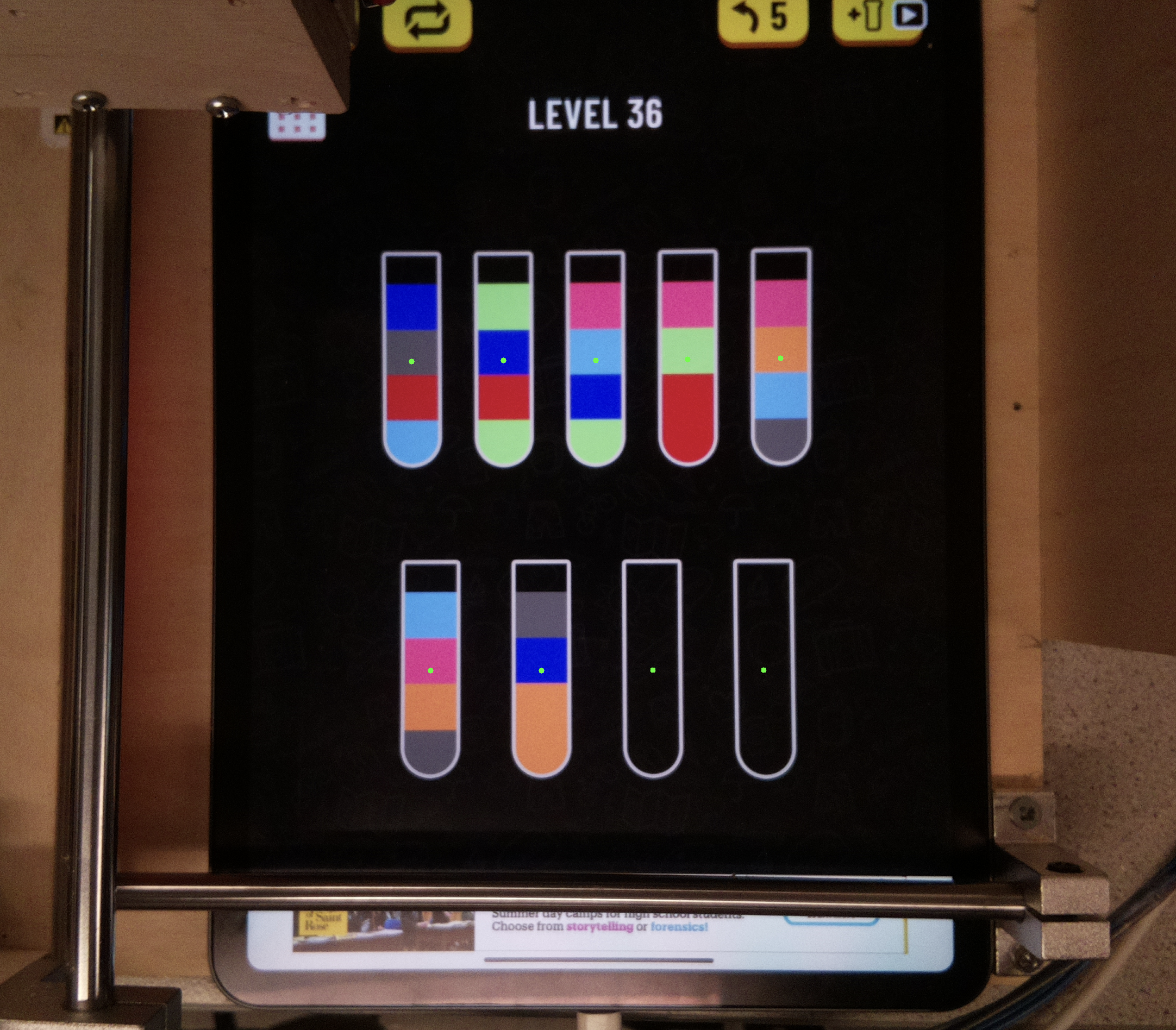
The Color-Tube game is a captivating puzzle that challenges players
to sort the tube using strategy and logic. At the begining of the
game, we have multiple tubes containing colored blocks and two empty
tubes. Each tube can hold up to four blocks, and there are four
blocks for each color in the game. The objective of the game is to
strategically use the empty tubes to rearrange the blocks of
different colors that are currently mixed in various tubes, placing
blocks of the same color into the same tube.
Our parents and friends all love this game. They enjoy spending
their leisure time playing it. However, as the game progresses, the
number of blocks and tubes increase, and some levels have trickly
obstacles that make it difficult to come up with a solution. To keep
the fun going, we need to create an automatic solving device that can
take photos, analyze the position and colors of the blocks in the
image, and use an efficient algorithm to generate the optimal
solving strategy. The device can use an iPencil to implement this
strategy in the game and complete the level.
Project Objective:
Researching an efficient algorithm to solve the game.
Using a camera to accurately identify block color and positions.
Building a structrue to securely hold an iPad and an iPencil.
Incorporating motors and sliders to enable the movemet of the
iPencil.
Ensure that all components are functioning properly to execute the
strategy successfully.
Design
The design process for this project includes writing the core
algorithm, designing the structural framework, and implementing the
computer vision (CV) routine.Throught this process, we encountered
serval challenges, with two main issues standing out.
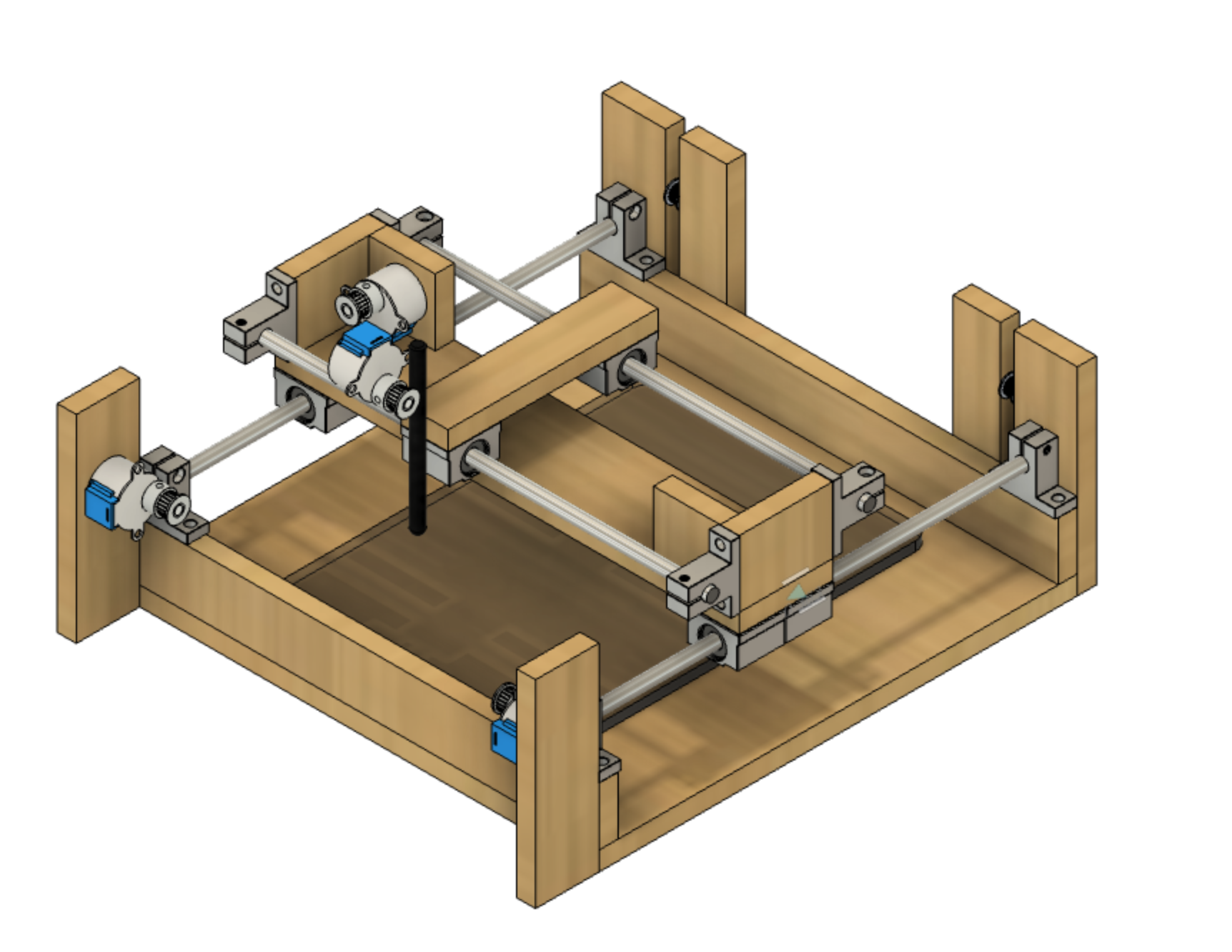
Firstly, the selection of materials and fixing elements ofr the
structrue posed a challenge. Initially, we planned to use acrylic
sheets as the structural material for the device, connected using
hot glue. Acrylic sheets were chosen for their transparency, as they
allow for better visualizatio of the algorithm execution from
various angles. To support this plan, we even created a strucural
diagram using Fusion 360. However, during discussions, we realized
that the acylic sheets were too thin, making it impossibel to drill
holes on the sides. Additionally, fixing the slide rail on the
acrylic sheets between problematic and was diffcult to accommodate
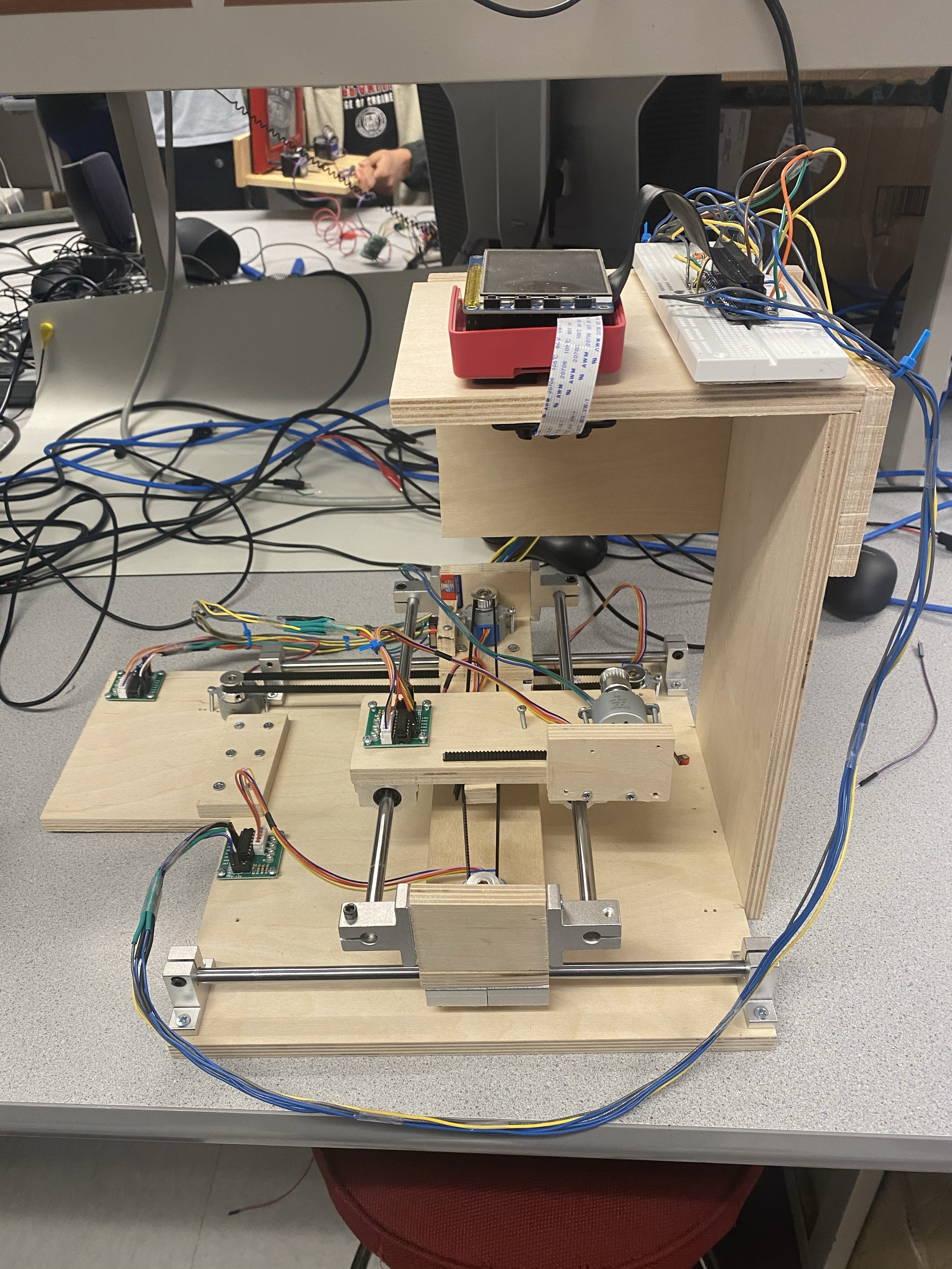
in the design adjustments.As a result, we had to urgently revise our
plan and opt for wooden boards and screws as the structural
materials.
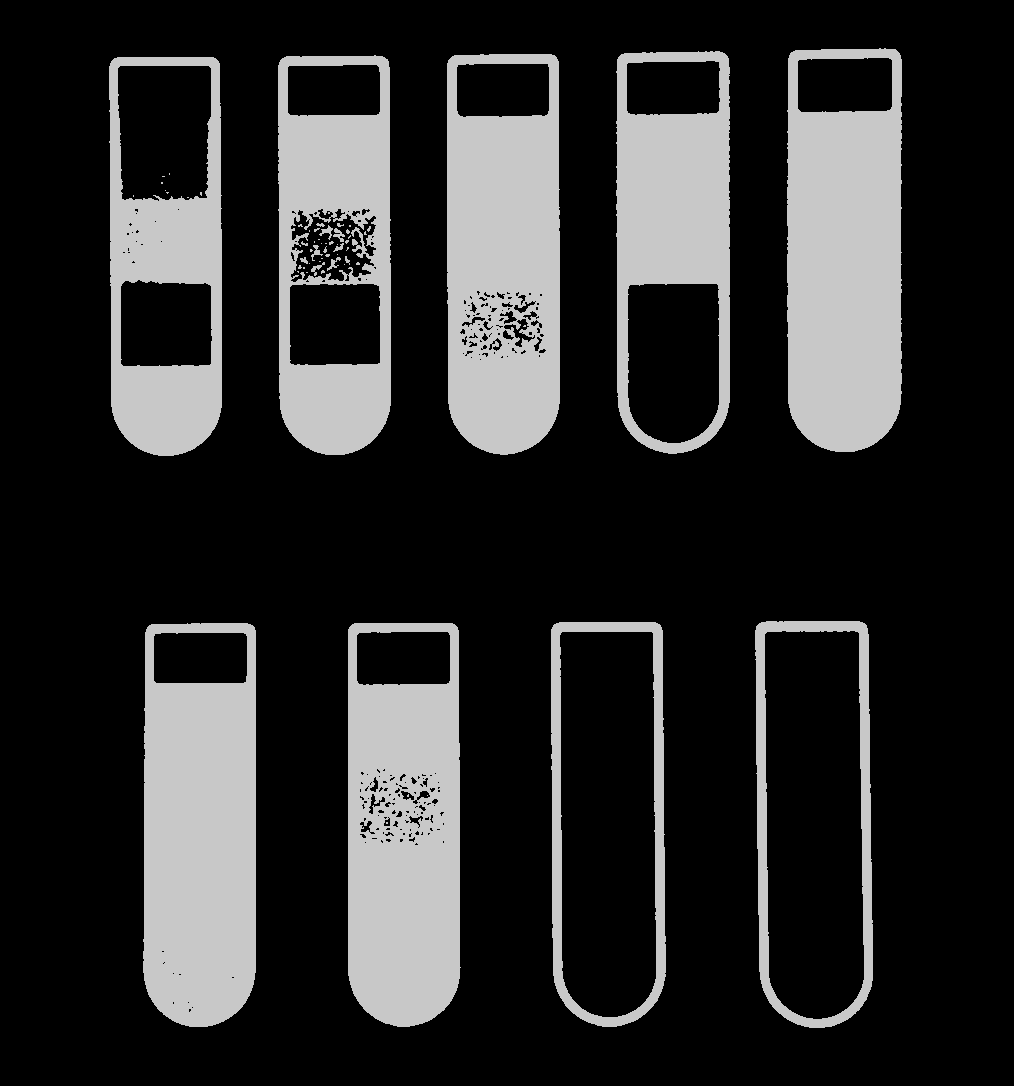
Secondly, concerning the CV routine, we encountered diffculties in
accurately identifying the contours of the tubes and blocks.
Sometimes, the blocks were not entirely detected, and at the other
times, there were interfering contours present. We later discovered
that proper adjustment of gray-scale levels was crucial for contour
recognition. Simple gray-scale adjustment often resulted in local
blurriness, causing some contours to be unrecognizable or unable to
be eliminted. Using black-and-white image proved to be more suitable
for identifying the countours of blocks in this game.
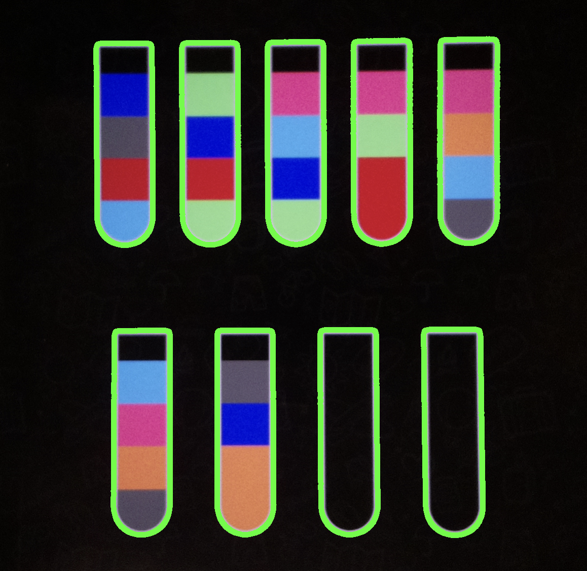
Next up, was detecting the tubes. After simple threshold and the
indentification of contours, we can easily use a warp transform on
the padding out image from the Ipad. This will give us the four
corners of the tube. We can then use the corners to find the center
of the tube and map it out for the motors.
Similarly, color recognition posed a challenge. The color range
recognition based on RGB values did bot provide helpful results.
This was mainly due to the presence of multiple colors in some
blocks, with RGB values that were relatively close. During our
learning process, we discovered the K-Means algorithm, which
calculates the average RGB values within a specific region. This
algorithm proved to be helpful in identifying colors with a sepcific
block area.
Motor control was relatively simple as we just had to have a tight
gear belt system to move linear blocks along a rail. Controlling it
was also simple as we did a simple calculation to estimate how many
steps for a 8 phase motor to move a certain distance.
Testing
The testing process involved several steps, including testing the
functionality of the motors and camera, constructing the structural
framework and slide rail, testing the functionality of the slide
rail, evaluating the positioning efffectiveness of the motors and
slide rail, testing the individual compoents' programs, and testing
the overall operation. Throughout this process, we encountered
numerous minor issues. These included problems such as the loosening
of motor belts, excessive friction between the slide rail and slider
component, the breaking of the fixing bolts, iPad positioning , and
camera installation. We continuously tried various methods and
drilled multiple positioning holes in the wooden boards. At this
point, we appreciate the decision to use wooden boards, as they
allowed us more flexibility for adjustments and modifications.
There are two anecdotes I can share. Firstly, regarding the motor,
during the initial perdormance testing, we found that our small
5-12V stepper motor was unable to move the belt out of our
expectation. This unexpected turn of events left us axious for an
entire day, to the point where we started considering larger motors
as an alternative. Hoever, due to time cinstriants, we couldn't
change our strategy. As a last resort, we conducted further tests
and discovered that the small stepper motor was indeed capable of
functioning properly. Yhis incident taught us the importance of
undering the connection methods for stepper motors. It was an
enlightening experience that reinforced the advice our professor had
given us in the first lab class: that experimental issues often
arise from small details, so it's crucial to remain attentive.
During the evening testing, the lab lights were too light, causing
reflections on the iPad and leading to incorrect recognitio by the
CV routine. We even added a light shield (wooden block) specifically
to address this issue. However, in the morning, the lighting was too
dim, and the contours couldn't be recognized. These incidents made
us realize the critivcal role of the camera's function. We later
discover that the PiCamera allowed for more detailed settings,
enabling us to adapt to different environmental conditions.
Despite encountering numerous challenges, our project proceeded
according to plan and was successfully completed
Result and Conclusion
The different components of our device performed quite well, and we
were initially concered that the dim lighting environment might
hinder the proper function of the CV routine. However, thankfully,
it worked successfully. We demostrated the device autonomously
completing two levels of the game in front of everyone without any
error, and I still remember the praise form the TA, "this project is
truly impressive." In my mind, our project is a success.
Future Work
Based on the advice from our professor, we could indeed make better
use of the camera's functions. Now the device takes a photo before
solving the game and uses this image fro position and color
detection, enabling the formulation of a solving strategy. However,
this approach presents a challenge: the device can only operate
based on a predetermined strategy, and any issues that arise cannot
be modified on the spot. The professor suggested that we ultilize
the video feature, allowing us to detect the completion of steps
during the game-solving process and adjust the strategy accordingly.
This is an excellent suggestion and will be our focus for future
work.
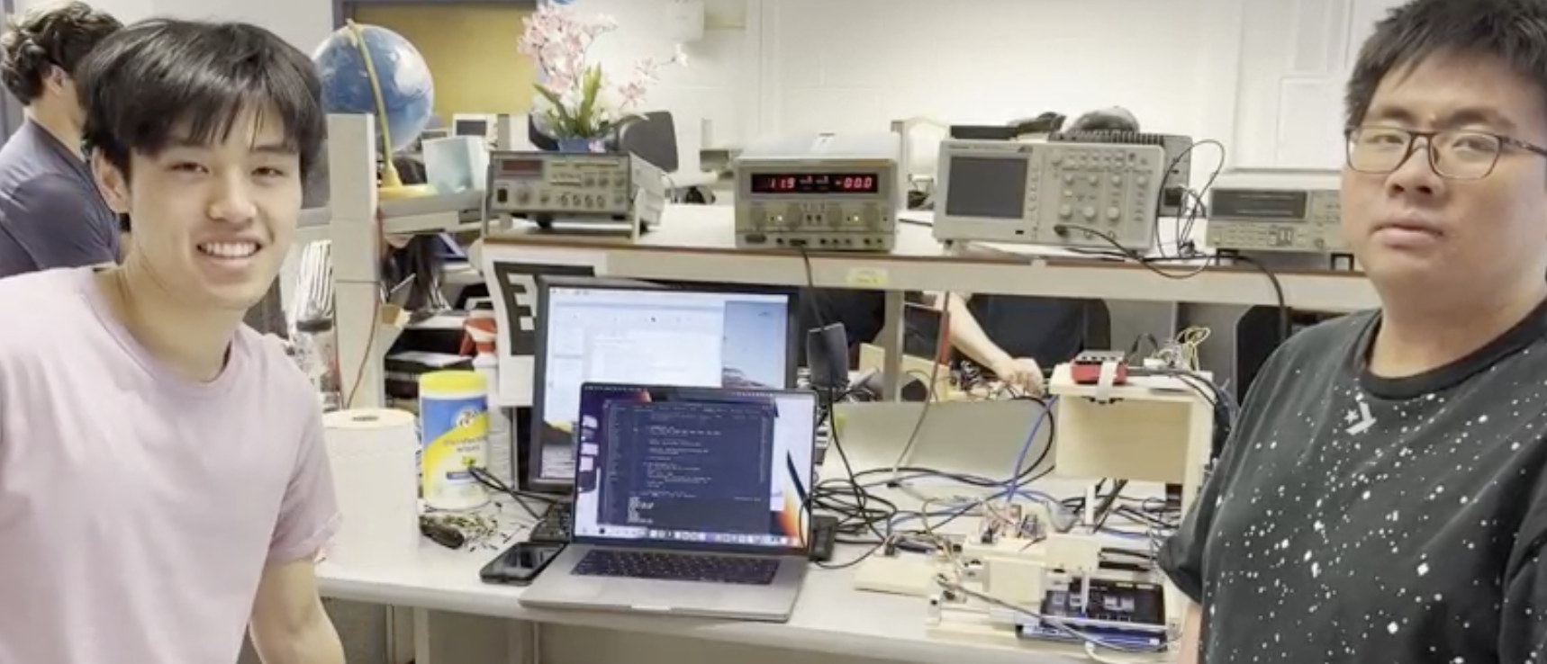
Work Distribution
Michael Liang
ml2226@cornell.edu
Writing the game-solving and CV algorithm, designing and
constructing the structure and testing the device function.
Erhe Zheng
ez226@cornell.edu
Parparing the components, helping to write the CV routine program, to build the structure,
and testing the motors and camera functionality.
      class Tubes:
      def __init__(self, img_path):
          self.img = cv2.imread(img_path)
          self.img_height, self.img_width, _ = self.img.shape
          self.pts = None
          self.warped_ipad = self.findIPAD(self.img)


          self.warped_height, self.warped_width, _ = self.warped_ipad.shape

          self.tube_centers_warped = []
          self.tube_arr, self.tube_imgs = self.findTube(self.warped_ipad)

          # Scale the tube centers
          self.tube_centers_original = [
              (int(pt[0] + self.pts[0][0]), int(pt[1] + self.pts[0][1])) for pt in self.tube_centers_warped]
          print(self.tube_centers_original)
          # Plot the transformed tube centers on the original image
          self.plotTubeCenters(self.tube_centers_original)

          self.colors, self.gamecolors = self.findTubeColors(self.tube_imgs)

          print(self.colors)

      def findByColor(self, img):

          # Define the lower and upper bounds for the darker black pixels
          lower_bound = np.array([0, 0, 0])
          # You can adjust this value to include more or fewer dark pixels
          upper_bound = np.array([50, 50, 50])

          # Apply the in-range filter to get the mask
          mask = cv2.inRange(img, lower_bound, upper_bound)
          gauss = cv2.GaussianBlur(mask, (3, 3), 0)
          # Perform morphological operations to remove noise if necessary
          kernel = cv2.getStructuringElement(cv2.MORPH_RECT, (3, 3))
          mask = cv2.morphologyEx(gauss, cv2.MORPH_CLOSE, kernel)
          return mask

      def findThreshold(self, img):
          gray = cv2.cvtColor(img, cv2.COLOR_RGB2GRAY)
          gauss = cv2.GaussianBlur(gray, (3, 3), 0)
          _, thresh_gaussian = cv2.threshold(
              gauss, 0, 200, cv2.THRESH_BINARY + cv2.THRESH_OTSU)
          cv2.imshow('gauss', thresh_gaussian)
          cv2.waitKey(0)
          kernel = cv2.getStructuringElement(cv2.MORPH_RECT, (3, 3))
          mask = cv2.morphologyEx(thresh_gaussian, cv2.MORPH_CLOSE, kernel)
          return mask

      def clkwBox(self, box):
          ysort = sorted(box, key=lambda x: (x[1]))
          if ysort[0][0] > ysort[1][0]:
              ysort[0], ysort[1] = ysort[1], ysort[0]
          if ysort[2][0] < ysort[3][0]:
              ysort[2], ysort[3] = ysort[3], ysort[2]
          return np.array(ysort)

      def four_point_transform(self, img, box):
          tl, tr, br, bl = box
          # print(tl)
          widthA = np.sqrt(((br[0] - bl[0]) ** 2)+((br[1]-bl[1])**2))
          widthB = np.sqrt(((tr[0] - tl[0]) ** 2)+((tr[1]-tl[1])**2))
          maxWidth = max(int(widthA), int(widthB))

          heightA = np.sqrt(((tr[0] - br[0]) ** 2)+((tr[1]-br[1])**2))
          heightB = np.sqrt(((tl[0] - bl[0]) ** 2)+((tl[1]-bl[1])**2))
          maxHeight = max(int(heightA), int(heightB))

          dst = np.array([[0, 0], [maxWidth-1, 0], [maxWidth-1,
                                                    maxHeight-1], [0, maxHeight-1]], dtype='float32')

          M = cv2.getPerspectiveTransform(np.float32(box), dst)
          wraped = cv2.warpPerspective(img, M, (maxWidth, maxHeight))
          return wraped

      def findTube(self, img, area_threshold=0.6):
          thresh = self.findThreshold(img)
          contours = cv2.findContours(
              thresh, cv2.RETR_EXTERNAL, cv2.CHAIN_APPROX_SIMPLE)
          cv2.imshow('thresh', thresh)
          cv2.waitKey(0)
          # plt.imshow(contours)
          # plt.show()
          # print(contours[0][1])
          a = cv2.drawContours(img, contours[0], -1, (0, 255, 0), 10)
          cv2.imshow('Contours', a)
          cv2.waitKey(0)
          # print(contours)
          rects = []
          tubes = []
          tubes_img = []

          for cnt in contours[0]:
              p = cv2.arcLength(cnt, True)
              epsilon = 0.01 * p
              poly = cv2.approxPolyDP(cnt, epsilon, True)
              rect = list(cv2.boundingRect(poly))
              rect = np.array(rect)
              if rect[3] > rect[2]:
                  rects.append(rect)

          rects = np.array(sorted(rects, key=lambda x: (x[0], x[1])))
          MAX_AREA = max(rects[:, 2]) * max(rects[:, 3])

          for rect in rects:

              if rect[2] * rect[3] > area_threshold * MAX_AREA:

                  rect[0] += rect[2]/8
                  rect[2] -= 2 * rect[2]/8
                  rect[1] += rect[3]/6
                  rect[3] -= rect[3]/6

                  center = [int((rect[0] + rect[0] + rect[2]) / 2),
                            int((rect[1] + rect[1] + rect[3]) / 2) - 30]

                  self.tube_centers_warped.append(center)

                  rect = [[rect[0], rect[1]], [rect[0] + rect[2], rect[1]],
                          [rect[0] + rect[2], rect[1] + rect[3]], [rect[0], rect[1] + rect[3]]]
                  tubes.append(rect)

                  tubes_img.append(self.four_point_transform(img, rect))

          return np.array(tubes), tubes_img

      def rgb_euclid(self, color1, color2):
          diff = np.array(color2) - np.array(color1)
          return math.sqrt(diff[0]**2 + diff[1]**2 + diff[2]**2)

      def add_padding(self, box, img, padding_ratio=1/10):
          height, width, _ = img.shape
          padding_x = width * padding_ratio * 1.3
          padding_y = height * padding_ratio * 2

          padded_box = []
          for point in box:
              x_offset = np.sign(point[0] - width / 2) * padding_x
              y_offset = np.sign(point[1] - height / 2) * padding_y

              # Modify padding based on the y-coordinate of the point
              if point[1] < height / 2:  # If point is in the upper half
                  y_offset *= 1  # Double the padding
              else:  # If point is in the lower half
                  y_offset *= 1  # Remove the padding

              if point[0] < width / 2:
                  x_offset *= 1.1
              else:
                  x_offset *= 1.5

              padded_point = [point[0] - x_offset, point[1] - y_offset]
              padded_box.append(padded_point)

          return np.array(padded_box, dtype=int)

      def plotTubeCenters(self, tube_centers):
          # Create a copy of the original image to draw on
          img_with_centers = self.img.copy()

          # Loop through each tube center
          for center in tube_centers:
              # Draw a circle at the center of the tube
              cv2.circle(img_with_centers, (int(center[0]), int(center[1])),
                         radius=5, color=(0, 255, 0), thickness=-1)

          # Display the image with the tube centers
          cv2.imshow('Image with Tube Centers', img_with_centers)
          cv2.waitKey(0)
          cv2.destroyAllWindows()

      def findIPAD(self, img):
          box = [[700, 400], [2000, 400], [2000, 1600], [700, 1600]]
          # Add padding to the box points

          # Apply the four-point transform
          self.pts = np.array(box, dtype=np.float32)

          warped_ipad = self.four_point_transform(img, box)
          print(warped_ipad.shape)

          return warped_ipad

      def plot_color(self, color):
          bar = np.zeros((50, 300, 3), dtype="uint8")
          startX = 0
          endX = startX + (300)
          cv2.rectangle(bar, (int(startX), 0), (int(endX), 50),
                        color.astype("uint8").tolist(), -1)
          startX = endX
          return bar

      def findTubeColors(self, tubes_img):
          colors = []
          gamecolors = []
          for tubes in tubes_img:
              color = []
              height = math.floor(tubes.shape[0]/4 - 1)
              width = math.floor(tubes.shape[1]/4 - 1)
              y_top = tubes.shape[0] - height
              y_bot = tubes.shape[0]
              h_pad = math.floor(width / 3)
              v_pad = math.floor(height / 5)
              box_index = 0
              while y_top > 0:
                  color_img = tubes[y_top + v_pad: y_bot - 3 *
                                    v_pad,  2 * h_pad: tubes.shape[1] - 2 * h_pad]

                  y_top -= height
                  y_bot -= height

                  color_img = color_img.reshape(
                      (color_img.shape[0] * color_img.shape[1], 3))

                  # Convert to np.float32
                  color_img = np.float32(color_img)

                  # Define criteria, apply kmeans()
                  criteria = (cv2.TERM_CRITERIA_EPS +
                              cv2.TERM_CRITERIA_MAX_ITER, 100, 0.2)
                  k = 1
                  _, _, centers = cv2.kmeans(
                      color_img, k, None, criteria, 10, cv2.KMEANS_RANDOM_CENTERS)

                  boxcolor = centers[0]

                  color_bar = self.plot_color(boxcolor)
                  box_index += 1

                  if len(gamecolors) == 0:
                      gamecolors.append(boxcolor)
                      color.append(1)
                  elif all(boxcolor < 50):
                      continue
                  else:
                      found = False
                      min = []
                      for index, c in enumerate(gamecolors):
                          if (self.rgb_euclid(boxcolor, c) < 50):
                              min.append([self.rgb_euclid(boxcolor, c), index])
                              found = True

                      if not found:
                          gamecolors.append(boxcolor)
                          color.append(len(gamecolors))
                      else:
                          color.append(min[np.argmin(min, axis=0)[0]][1] + 1)
              box_index = 0
              colors.append(color)

          return colors, gamecolors
Game Class
solves game after finding tube details
      from tubes import Tubes

      MAX_HEIGHT = 4


      class Game(Tubes):
          def __init__(self, img_path):
              super().__init__(img_path)
              print(self.warped_ipad.shape)
              self.answer = []

          def algorithm(self):
              tubes = self.colors
              tubes = self.tubes2String(tubes)
              for i, t in enumerate(tubes):
                  if (i < len(tubes) - 1):
                      answer = []
                      new_game = copy.copy(tubes)
                      cond, answer = self.solve([], new_game, answer)

                      # answers are pushed in reverse order, so reverse it to get answer from beginning
                      answer.reverse()

                      if len(answer) > 0:
                          for ind, a in enumerate(answer):
                              print(a)
                              self.answer.append(a)
                              if self.can_pour(tubes[a[0]], tubes[a[1]], tubes):
                                  self.pour(tubes[a[0]], tubes[a[1]])

                          break
                      else:
                          first_tube = tubes.pop()
                          tubes.insert(0, first_tube)
                          # print(self.tubes)
              return tubes

          def tubeMovesToPos(self):
              move_pos = []
              for move in self.answer:
                  for m in move:
                      move_pos.append(self.tube_centers_original[m])
              return move_pos
              # count the number of base colors in tube

          def count_color(self, tube, color):
              count = 0
              for c in tube:
                  if c == color:
                      count += 1
              return count

          # check if all tubes have been sorted

          def is_solved(self, tubes):
              for t in tubes:
                  if (len(t) > 0):
                      if (len(t) < MAX_HEIGHT):
                          return False
                      if (self.count_color(t, t[0]) != MAX_HEIGHT):
                          return False
              return True

          # check if source tube can pour into destination tube

          def can_pour(self, source, destination, tubes):
              if len(source) == 0 or len(destination) == MAX_HEIGHT:
                  return False
              source_colors = self.count_color(source, source[0])

              if source_colors == MAX_HEIGHT:
                  return False

              destination_colors = 0
              if len(destination):
                  destination_colors = self.count_color(destination, destination[0])

              # removes unnecessary pours to already filled tubes
              if self.count_color(source, source[-1]) + len(destination) > MAX_HEIGHT:
                  return False

              better_option_found = False
              # attempting to look at other tubes
              for ind, tube in enumerate(tubes):
                  if tube == destination:
                      continue
                  # check if a different tube is better to move to
                  tube_colors = self.count_color(
                      tube, tube[0]) if len(tube) > 0 else 0
                  if len(tube) != MAX_HEIGHT and len(tube) > 0 and source[-1] == tube[-1] and tube_colors > destination_colors:
                      # better option in tubes, so therefore we don't pour here
                      better_option_found = True
                      break

              if better_option_found:
                  return False

              if not len(destination):  # empty empty list
                  if source_colors == len(source):
                      return False
                  return True

              return source[-1] == destination[-1]

          # pour source tube into destination tube

          def pour(self, source, destination):

              # always move one
              top = source.pop()
              destination.append(top)
              while len(source) > 0:
                  # look at next and compare
                  next = source[len(source) - 1]
                  if (next == top):
                      destination.append(source.pop())
                  else:
                      break

          def tubes2String(self, tubes):
              tubeStr = []
              for t in tubes:
                  newTube = []
                  for c in t:
                      newTube.append(str(c))
                  tubeStr.append(newTube)
              return tubeStr

          # recursively solve the tubes by storing visited sorts

          def solve(self, visited_sorts, current_sort, answer):
              visited_sorts.append(self.tubes2String(current_sort))

              for i1, t1 in enumerate(current_sort):
                  for i2, t2 in enumerate(current_sort):
                      if (i1 != i2 and self.can_pour(t1, t2, current_sort)):
                          new_sort = copy.deepcopy(current_sort)
                          if self.can_pour(new_sort[i1], new_sort[i2], new_sort):
                              self.pour(new_sort[i1], new_sort[i2])

                              if (self.is_solved(new_sort)):
                                  print('SOLVED')
                                  answer.append([i1, i2])
                                  return True, answer
                              if (self.tubes2String(new_sort) not in visited_sorts):
                                  continue_sort, updated_answer = self.solve(
                                      visited_sorts, new_sort, answer)
                                  if (continue_sort):
                                      answer.append([i1, i2])
                                      return True, updated_answer

              return False, answer